|
FEATURES
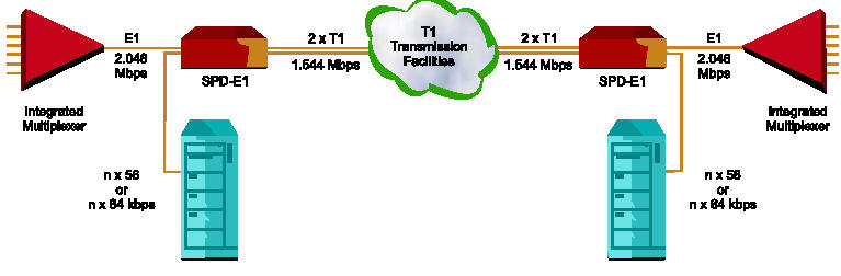
- The SPD-E1 Rate and Interface Converter enables E1
equipment to utilize two T1 transmission links, by converting any E1 frame
(2.048 Mbps) into two T1 frames(1.544 Mbps). SPD-E1 is transparent to the
E1 framing pattern.
- Jitter attenuation on each side guarantees smooth,
jitter-free operation.
- T1 parameters include D4 or ESF framing and AMI or
B8ZS codes. In the ESF format, T1 main link statistics are stored in
memory, in compliance with both ANSI and AT&T standards, and may be
retrieved by the service supplier, or by the user via the supervisory
port.
- Timing options cover all timing situations. These
include:
- Transparent timing: T1 transmit clock of
both links is locked to E1 receive clock, and E1 transmit clock is
locked to T1-A receive clock.
- Loopback timing: T1 transmit clock for
both links is derived from T1-A receive clock. E1 transmit clock is
derived from E1 receive clock.
- Internal clock: Internal oscillator is the
source for both E1 and T1 transmit clocks.
- Station clock: The source for both the E1
and T1 transmit clocks is the framed/unframed all "1"s T1 (AMI).
- Independent elastic buffering in each direction
compensates for short term deviations in timing sources. Buffer size is
 16
E1 frames (4096
bits). 16
E1 frames (4096
bits).
- The E1 frame (256 bits) is equally divided between
both T1 frames, utilizing timeslots 1 to 16 of each T1 link. Spare
bandwidth may accommodate an additional DTE data channel.
- Data rates for the data channel are selectable for
any multiple of 56 or 64 kbps, up to 1024 kbps. The DTE channel interface
is available as V.35 or RS-530/RS-422.
- Setup, control and monitoring of status and
diagnostic information can be performed via an ASCII terminal. Setup of
the basic unit can also be performed via internal jumpers. Automatic
dial-up is also supported whenever an alarm event occurs.
- Diagnostic loopbacks, activated either from the
front panel or from the ASCII terminal, include:
- E1 loopback towards the local DTE;
- T1 loopback on both links, towards the remote DTE;
- T1 network line loopback with carrier code
activated on each T1 link.
- SPD-E1 is available as a desktop unit, with rack
mount hardware for mounting in a 19'' rack.
.SPECIFICATIONS
- Converts an E1 frame into two T1 frames
- Enables E1 equipment to operate over T1 facilities
- Additional data channel: n x 56 or n x 64 kbps
- Transparent to E1 framing
- Controlled slip for buffer overflow/underflow
- Loopback capabilities
- Built-in CSUs on the T1 links
- T1 interface complies with AT&T TR-62411, PUB 54016
- E1 interface complies with ITU Rec. G.703, G.823
- 24 hour storage of T1 line diagnostics
- Automatic dial-up upon alarm event
SPD-E1/*/#
E1/T1 Rate and Interface Converter
| * |
Specify:
115 for 115 VAC supply
48 for -48 VDC power supply |
| # |
Specify data channel interface:
V35 for V.35 interface
530 for RS-530/422 interface
(Default is V.35) |
ORDERING
SPD-E1/115/530
SPD-E1/115/V35
SPD-E1/48/530
SPD-E1/48/V35
APPLICATIONS
|