|
FEATURES
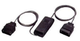
- MTE is a Miniature Elastic Buffer, enabling the
connection of two independently clocked DCEs. When two internally clocked
devices exchanging data cannot be clocked externally, MTE is used as an
interface between them.
- MTE is available in five models. Two models, MTE/V24
and MTE/V35, have the electrical and functional characteristics of the
V.24/RS-232 and V.35 interface, respectively. Three other models have the
electrical characteristics of the V.11/RS-422 interface, while complying
with different standards for the functional/physical characteristics:
MTE/X21-complies with X.21 and has a 15-pin
connector
MTE/422- complies with RS-449/422 or V.36 and has a 37-pin connector
MTE/530 -complies with RS-530 and has a 25-pin connector
- MTE utilizes two 512-bit buffers to reduce errors
caused by drift between the two DCE clocks. Upon overflow or underflow,
MTE automatically restarts at the middle of the buffer.
- A schematic diagram in Figure 1 shows the flow of
data clocking in and out of the buffers.
- Note: V.35 and V.24/RS-232 pin assignment is
not shown in the diagram, for the sake of simplicity.
DCE to DCE connection
Two internal 512-bit buffers
Data rates up to 2048 kbps
Five models available:
- MTE/V24 - for RS-232 or V.24/V.28
- MTE/V35 - for V.35
- MTE/X21 - for X.21
- MTE/422 - for RS-422 or V.36
- MTE/530 - for RS-530
Easy to install
No AC power required
Compact, lightweight
The device works as follows:
The Receive Clock of DCE-A clocks Receive Data into buffer A. The Transmit
Clock of DCE-B clocks Transmit Data out of buffer A.
The Receive Clock of DCE-B, clocks Receive Data into buffer B. The Transmit
Clock of DCE-A clocks Transmit Data out of buffer B.
For MTE/X.21, Receive Clock and Transmit Clock of each side are connected to
the "Signal Timing" signal of the DCEs.
Note that all MTE models delay the data only, while the control signals are
just wired through (see Figure 1). Care should be taken in designing
applications where the data and control signals must have the same delay.
The MTE interface for each balanced pair can operate with cables of up to 2m
(7 ft) on each side (15m for MTE/V.24).
MTE operates without connection to the mains supply, using low power derived
from the DCE interface signals.
MTE/V24
Miniature Elastic Buffer for V.24/RS-232 interface
MTE/V35
Miniature Elastic Buffer for V.25 interface
MTE/X21
Miniature Elastic Buffer for X.21 interface
MTE/422/*
Miniature Elastic Buffer for RS-449/422 interface
MTE/530
Miniature Elastic Buffer for RS-530 interface
* Specify: - M for two male connectors
- F for two female connectors
ORDERING
MTE-1
MTE-1/V35
MTE-2
MTE/530
MTE/V24
MTE/V35
MTE/V35/M-M
MTE/X21/F
MTE/X21/M
APPLICATIONS
|