FEATURES
- T1 or Fractional T1 CSU/DSU
- Supports one or two data ports with selectable sync
data rates: n x 56, n x 64 kbps
- Optional sub-T1 drop & insert port for PABX
connectivity
- Failure immune sub-T1 ensuring uninterrupted
service (G.703 only)
- Data interfaces: V.35, RS-530, V.36/RS-449 or X.21
- Optional high performance built-in Ethernet bridge
- SNMP agent
- In-band remote management
- Dial-in option for remote out-of-band management
- Dial-out for alarm report
- T1 main link with integral CSU
- Optional fiber optic main link with the following
interfaces:
- 850 nm LED for multimode
- 1300 nm LED for single mode
- 1300 nm laser for single mode
- 1550 nm laser for extended range over single mode
- Framing format (main link and sub-T1 port): D4, ESF
and unframed
- Zero suppression (main link and sub-T1 port): B7ZS,
B8ZS and transparent
- T1 interface complies with: AT&T TR62411, TR62421,
ANSI T1.403 and AT&T 54016 (local support)
- Enhanced diagnostics include:
- User activated local and remote loopbacks
- Integrated BER tester
- Fractional T1 inband loop
- Stores 24 hours of T1 network performance
monitoring and last 100 alarms
- Relay activation upon alarm event
- Alarm mask configurable for any alarm
BASIC UNIT
- The basic unit includes power supply, T1 link with
integral CSU and one data port.
- The T1 interface is compatible with virtually all
carrier provided T1 services, including ASDS from AT&T and complies with
TR-62421. The T1 interface supports D4 and ESF framed formats. Zero
suppression over the line is selectable for either transparent, B7ZS or
B8ZS. The integral CSU ensures a range of up to one mile.
- FCD-T1 can be ordered with a fiber optic link,
which eliminates the need for an external fiber optic modem. The fiber
optic link provides a secure link in hazardous or hostile environments. It
complies with ITU standards G.921 and G.956.
- Four fiber optic interfaces are available:
- 850 nm LED for use over multimode fiber at
distances up 3 miles
- 1300 nm LED for use over single mode fiber at
distances up to 29 miles
- 1300 nm laser diode for use over single mode
fiber at distances up to 38 miles
- 1550 nm laser diode for use over single mode
fiber for extended range up to 62 miles.
- Timeslot assignment is programmable, allowing data
from each data port and from the sub-T1 port to be placed into timeslots
(DS0s), consecutively. FCD-T1 also provides additional flexibility, by
giving full user control over the data ports timeslot allocation, without
restrictions.
- Multiple clock source selection ensures maximum
flexibility for supporting different applications. The T1 main link may be
clocked from the recovered receive clock, from an internal oscillator,
from one of the data ports or from the sub-T1 port.
- Bypassing the sub-T1 port to the main link
(non-fiber optic), ensuring uninterrupted service to the sub-T1 port,
provides immunity to hardware and power failure.
- FCD-T1 is available as a standalone unit. A rack
mount adapter kit enables installation of one or two standalone units,
side by side in a 19" rack.
USER INTERFACE
- The following data port interfaces can be ordered:
V.35, RS-530, V.36/RS-449 or X.21. The ports can operate in the following
clock modes:
- The optional built-in Ethernet bridge is a high
performance remote, self-learning bridge. It is ideal as a LAN extender or
segmenter over T1 link applications. The LAN table stores up to 10,000
addresses and is automatically updated. Filtering and forwarding is
performed at the maximum theoretical rate of 15,000 pps (wire speed) and
the buffer can hold 256 frames with a throughput latency of 1 frame.
Filtering can be disabled for extender or segmenter applications. The
Ethernet port is available with either 10BaseT (UTP) or 10Base2 (BNC)
interface. The Ethernet port with 10BaseT operates in full duplex mode,
while the one with 10Base2 operates in half duplex.
- The optional sub-T1 port can be configured with D4
or ESF framing, while the T1 main link framing is ESF. This enables, for
example, connection of T1 D4 equipment over a T1 network.
MANAGEMENT & MAINTENANCE
- Setup, control and monitoring of status and
diagnostics information can be activated via:
- Front panel LCD with three push-buttons
- Menu-driven management
- ASCII terminal connected to the async control
port command line interpreter
- SNMP management connected to the async control
port.
- FCD-T1 has an internal SNMP agent and can be
controlled by any generic SNMP station or by the RADview SNMP network
management application.
- FCD-T1 supports dial-in, dial-out modem
connections. These connections can be used for remote out-of-band
configuration, monitoring and for sending callout alarm messages.
- Inband management can be performed using the
Facility Data Link (FDL) in the ESF framing format or using a dedicated
timeslot. This allows setup, monitoring and diagnostics of the remote
unit. In-band access by using the FDL is possible only if the FDL is
passed transparently end-to-end.
- Maintenance capabilities include user activated
local and remote loopbacks at the T1 main link, sub-T1 and data ports.
FCD-T1 responds to network activated loops (PLB, LLB) when configured as
CSU. The user can activate a BER test for each data port individually.
Each data port responds to an ANSI FT1 in-band loop code, generated from
the remote FCD-T1 or DXC in a specific bundle of timeslots allocated only
to that port.
- When operating in the ESF format, T1 network
statistics are stored in memory in compliance with both ANSI and AT&T
standards. The statistical information may be retrieved by the service
supplier (ANSI only) or locally through the control port.
FCD-T1/*/~/&/%/#+
T1 or Fractional T1 CSU/DSU
| * |
Specify optional
drop & insert sub-link:
S1 for T1 sub-link |
| ~ |
Specify power supply voltage:
AC for 115 VAC and 230 VAC
48 for -48 VDC |
| & |
Specify data port interface:
530 for RS-530 interface
V35 for V.35 interface
X21 for X.21 interface
449 for RS-449 interface |
| % |
Specify optional 2-nd data port interface:
530 for RS-530 interface
V35 for V.35 interface
X21 for X.21 interface
449 for RS-449 interface
232 for RS-232 interface
ETU for UTP Ethernet bridge (10BaseT)
ETB for BNC Ethernet bridge (10Base2) |
| #+ |
Specify optional optical interface: |
| # |
ST for ST connector
SC for SC connector
FC for FC/PC connector |
| + |
85 for 850 nm, multimode
13 for 1300 nm, single mode
13L for 1300 nm, single mode, laser diode
15L for 1550 nm, single mode, laser diode
(Default is G.703 electrical interface) |
Cables
The following cables convert the
25-pin channel connector into the respective interface. Cable length is 2m
(6 ft), unless otherwise indicated.
CBL-HS2V1 to connect a V.35 DTE using DCE
clock mode*
CBL-HS2V2 to connect a V.35 DCE using
DTE1 clock mode*
CBL-HS2V3 to connect a V.35 DCE using
DTE2 clock mode*
CBL-HS2R1 to connect an RS-449 (V.36) DTE
using DCE clock mode*
CBL-HS2R2 to connect an RS-449 (V.36) DCE
using DTE1 clock mode*
CBL-HS2R3 to connect an RS-449 (V.36) DCE
using DTE2 clock mode*
CBL-HS2X1 to connect an X.21 DTE using
DCE clock mode*
* DCE clock mode: FCD-T1 provides both
transmit and receive clocks
DTE1 clock mode: FCD-T1 provides transmit
clock, attached DCE provides receive clock
DTE2 clock mode: attached DCE provides both
transmit and receive clocks
SPECIFICATIONS
-
FCD-T1/*/~/&/%/#+
T1 or Fractional T1 CSU/DSU
| * |
Specify optional
drop & insert sub-link:
S1 for T1 sub-link |
| ~ |
Specify power supply voltage:
AC for 115 VAC and 230 VAC
48 for -48 VDC |
| & |
Specify data port interface:
530 for RS-530 interface
V35 for V.35 interface
X21 for X.21 interface
449 for RS-449 interface |
| % |
Specify optional 2-nd data port interface:
530 for RS-530 interface
V35 for V.35 interface
X21 for X.21 interface
449 for RS-449 interface
232 for RS-232 interface
ETU for UTP Ethernet bridge (10BaseT)
ETB for BNC Ethernet bridge (10Base2) |
| #+ |
Specify optional optical interface: |
| # |
ST for ST connector
SC for SC connector
FC for FC/PC connector |
| + |
85 for 850 nm, multimode
13 for 1300 nm, single mode
13L for 1300 nm, single mode, laser diode
15L for 1550 nm, single mode, laser diode
(Default is G.703 electrical interface) |
Cables
The following cables convert the
25-pin channel connector into the respective interface. Cable length is 2m
(6 ft), unless otherwise indicated.
CBL-HS2V1 to connect a V.35 DTE using DCE
clock mode*
CBL-HS2V2 to connect a V.35 DCE using
DTE1 clock mode*
CBL-HS2V3 to connect a V.35 DCE using
DTE2 clock mode*
CBL-HS2R1 to connect an RS-449 (V.36) DTE
using DCE clock mode*
CBL-HS2R2 to connect an RS-449 (V.36) DCE
using DTE1 clock mode*
CBL-HS2R3 to connect an RS-449 (V.36) DCE
using DTE2 clock mode*
CBL-HS2X1 to connect an X.21 DTE using
DCE clock mode*
* DCE clock mode: FCD-T1 provides both
transmit and receive clocks
DTE1 clock mode: FCD-T1 provides transmit
clock, attached DCE provides receive clock
DTE2 clock mode: attached DCE provides both
transmit and receive clocks
ORDERING
FCD-T1/48/1/530
FCD-T1/48/1/ETB
FCD-T1/48/1/V
FCD-T1/48/2/V
FCD-T1/48/V35/ETU
FCD-T1/AC/1/449
FCD-T1/AC/1/530
FCD-T1/AC/1/ETB
FCD-T1/AC/1/ETU
FCD-T1/AC/1/R/ST/85
FCD-T1/AC/1/ST/13
FCD-T1/AC/1/ST/85
FCD-T1/AC/1/V
FCD-T1/AC/1/V/ST/13
FCD-T1/AC/1/V/ST/85
FCD-T1/AC/1/X
FCD-T1/AC/2/530
FCD-T1/AC/2/530/ST/85
FCD-T1/AC/2/R
FCD-T1/AC/2/R/ST/13
FCD-T1/AC/2/V
FCD-T1/AC/2/V/FC13
FCD-T1/AC/2/V/ST13
FCD-T1/AC/2/X
FCD-T1/AC/530/ETU/ST13
FCD-T1/AC/530/MO
FCD-T1/AC/ETU/V
FCD-T1/S1/48/ETU
FCD-T1/S1/48/ETU/V
FCD-T1/S1/AC/1/449
FCD-T1/S1/AC/1/530
FCD-T1/S1/AC/1/V
FCD-T1/S1/AC/2/530
FCD-T1/S1/AC/2/V
FCD-T1/S1/AC/2/X
FCD-T1/S1/AC/ETU/V
FCD-T1M/48/U/V35
FCD-T1M/AC/U/ETUR
FCD-T1M/AC/U/V35
FCD-T1M/S1/48/UTP/V35/FC13
FCD-T1M/S1/AC/U/ETU/R
FCD-T1M/S1/AC/U/V35
APPLICATION
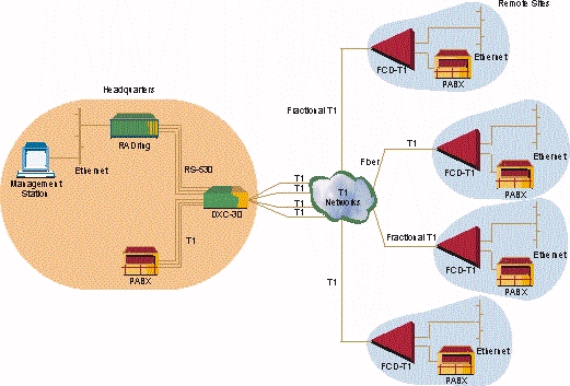
Figure1. Extended Ethernet Management over
T1 Network
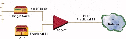
Figure 2. Connection of LAN Traffic
Together with PABX Traffic to T1 Network
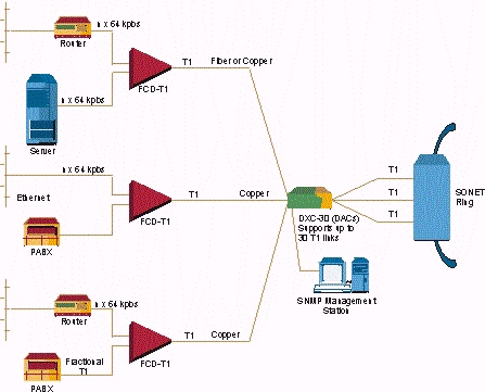
Figure 3. SONET Access Solution for
Multiple Remote Sites
|