Features
- The ASM-45, Short Range Modem, operates
synchronously, full duplex over unconditioned lines, at a range of up to
5.5 km (3.5 miles). ASM-45 operates at seven selectable data rates up to
768 kbps.
- The digital interfaces available are:
- RS-530
- V.35
- X.21
- V.24/RS-232 (up to 64 kbps only)
- G.703 Codirectional (64 kbps).
- Conditioned diphase modulation (EUROCOM Std. D1)
provides immunity to background noise, eliminates normal line distortion
and enables efficient transmission and reception of serial data over
twisted pair cable.
- Transmit timing is provided either internally, or
is derived externally from the data terminal or from the receive signal.
Receive timing is regenerated from the received signal.
- ASM-45 features V.54 diagnostic capability to
perform local analog loopback, and local and remote digital loopback
tests. Loopback is controlled by either a manual switch or via the digital
interface signals (excluding X.21 and G.703 interfaces). The front panel
switch generates a pseudo-random test pattern (511 bits) according to ITU,
for testing end-to-end connectivity. An ERROR LED flashes for each bit
error.
- ASM-45 incorporates interface circuits for the
terminal/computer, an automatic equalizer, and a modulator/demodulator.
Line coupling is through isolation transformers which, in conjunction with
other circuitry, protect against AC or DC overvoltages.
- ASM-45 is available as a standalone (desk-top) unit
or as a card for the ASM-MN-214 19" modem rack. DTE connectors on the rack
are 25-pin D-type, female. Modems with X.21 or V.35 interface require an
external mechanical adapter. CIA/X.21 can be ordered for converting two
adjacent DB-25 connectors to two X.21 15-pin connectors, or CIA/V.35/1 for
converting one DB-25 connector to a V.35 34-pin connector.
Specifications
- Synchronous transmission over 4-wire
- Selectable data rates: 64, 128, 192, 256, 384, 512
or 768 kbps
- Range up to 5.5 km / 3.5 miles at 64 kbps over 24
AWG cable
- Carrier control
- V.54 diagnostics
- Internal test pattern generator (V.52) and special
error LED
- Variety of digital interfaces: RS-530, V.35, X.21,
V.24 (64 kbps only) or G.703 Codirectional (64 kbps)
ASM45/*/#
Short Range Modem, standalone unit
ASM-45R/#
Short Range Modem card for the ASM-MN-214 19" modem rack
Note: When using V.35 or X.21 interfaces, the CIA adapter is required.
ASM-MN-214/*/
19" modem rack for 14 modem cards
| * |
Specify supply voltage for the standalone and the
rack's main power supply:
115 for 115 VAC
230 for 230 VAC
48 for -36 to -72 VDC |
| # |
Specify interface:
V35 for V.35 interface
X21 for X.21 interface
530 for RS-530 interface
V24 for V.24/RS-232 interface
G703 for G.703 Codirectional, card version
G703/TB for G.703 Codirectional, with terminal block (standalone)
G703/RJ for G.703 Codirectional, with RJ-45 (standalone) |
|
Specify second, redundant power supply:
For ordering options, see main power supply. |
CIA/&
Connector Interface Adapter for the ASM-MN-214 19" rack
| & |
Specify connector:
V35/1 for adapting one modem card's 25 pin connector to one V.35,
34-pin connector
X21 for adapting two adjacent modem cards' 25-pin connectors to
two X.21, 15-pin connectors |
ORDERING INFO
ASM-45
APPLICATION
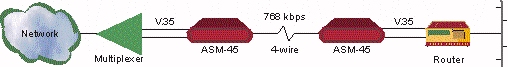
Table 1. Approximate Range
| Data Rate |
19 AWG |
22 AWG |
24 AWG |
26 AWG |
| Kbps |
km |
miles |
km |
miles |
km |
miles |
km |
miles |
| 768 |
1.8 |
1.1 |
1.2 |
0.7 |
1.0 |
0.6 |
0.8 |
0.5 |
| 512 |
2.5 |
1.5 |
2.0 |
1.2 |
1.5 |
1.0 |
1.0 |
0.6 |
| 384 |
4.5 |
2.8 |
3.0 |
1.8 |
2.5 |
1.5 |
2.0 |
1.2 |
| 256 |
6.0 |
3.8 |
4.5 |
2.8 |
3.5 |
2.0 |
3.0 |
1.8 |
| 192 |
6.5 |
4.0 |
5.0 |
3.0 |
4.0 |
2.5 |
3.0 |
1.8 |
| 128 |
9.0 |
5.5 |
6.5 |
4.0 |
5.0 |
3.0 |
3.5 |
2.0 |
| 64 |
11.5 |
7.0 |
7.5 |
4.5 |
5.5 |
3.5 |
3.5 |
2.0 |
|