Features
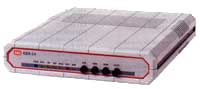
- The ASM-24, High Speed Short Range Modem, operates
synchronously at full or half duplex, over unconditioned twisted pair,
4-wire lines. It has a range of up to 26.4 km (16.5 miles), depending upon
the wire gauge and data rate used (see Table 1). ASM-24 operates at data
rates from 48 up to 144 kbps (48-128 kbps for V.24).
- The line code used, PR4 (Partial Response, Class
IV), reduces bandwidth requirements, providing excellent performance and
long range.
- ASM-24 incorporates interface circuits for the DTE,
an automatic equalizer, a modulator, a demodulator, and diagnostics
circuitry. It is coupled to the line through isolation transformers which,
in conjunction with other circuitry, protect against AC or DC overvoltages.
The protection circuitry enables operation even when DC is connected to
the line.
- Transmit timing is provided internally, or is
derived externally from the data terminal or receive signal. Receive
timing is derived from the line received signal.
- ASM-24 features V.54 diagnostic capabilities to
perform local analog loopback, and local and remote digital loopbacks. The
loops can be activated manually from the front panel or via control
signals from the digital interface.
- A built-in Bit Error Rate Tester (BERT) enables
complete testing of both modems and the line. A front-panel switch
generates a pseudo-random test pattern (511 bits) according to ITU V.52,
for testing end-to-end connectivity. When a bit error is detected, the ERR
LED flashes.
- ASM-24 is available as a standalone unit or as a
rack-mount card for the ASM-MN-214 19" modem rack. The rack can carry up
to 14 cards and is supplied with 25-pin D-type connectors.
- Optional rack mounting hardware is available for
mounting one or two standalone units in a 19" modem rack.
Specifications
- High-speed, extended range, baseband modem
- Synchronous operation, full or half duplex
- Selectable data rates, from 48 to 144 kbps
- Range up to 10 km (6.2 miles) at 64 kbps, over 24
AWG
- Carrier control
- V.54 diagnostics:
Internal test pattern generator and error detection
- Interface options for:
V.24/RS-232, V.35, V.36/RS-449, RS-530,
X.21, G.703 Codirectional (64 kbps), and built-in Ethernet bridge
- Line protection circuits
ASM-24SA/*/#
Short Range Modem, standalone unit with internal power supply
ASM-24R/#
Short Range Modem card for the ASM-MN-214 19" rack
Note: When using V.35 or X.21 interfaces, the
CIA adapter is required.
ASM-MN-214/*/&
19" rack for 14 modem cards
| * |
Specify supply voltage for a
standalone unit and main power
supply for the modem rack:
100 for 100 VAC
115 for 115 VAC
230 for 230 VAC
48 for -48 VDC
24 for 24 VDC |
| # |
Specify interface:
V24 for V.24 or RS-232
V35 for V.35
V36 for V36 or RS-449
530 for RS-530
(V.11/RS-422 on 25-pin)
X21 for X.21
ETH UTP for built-in Ethernet/802.3 bridge with RJ-45 connector
ETH BNC for built-in Ethernet/802.3 bridge with BNC connector
G.703/TB for G.703 Codirectional (64 kbps) with terminal block
G.703/RJ for G.703 Codirectional (64 kbps) with RJ-45 connector |
| & |
Specify second, redundant power supply for the
rack:
100 for 100 VAC
115 for 115 VAC
230 for 230 VAC
48 for -48 VDC
24 for 24 VDC |
RM-17
Hardware for mounting one or two standalone units in a 19" rack
CIA/V35
Adapter for changing one modem card's 25-pin connector into one V.35
connector
CIA/X21
Adapter for changing two adjacent modem cards' 25-pin connectors to two
X.21 connectors
ORDERING INFO
ASM24/115/530
ASM24/115/G703/TB
ASM24/115/UTP
ASM24/115/V24
ASM24/115/V35
ASM24/115/V36
ASM24/115/X21
ASM24/230/G703/RJ
ASM24/230/G703/TB
ASM24/230/RS530
ASM24/230/UTP
ASM24/230/V24
ASM24/230/V35
ASM24/230/X21
ASM24/48/V24
ASM24/48/V36
ASM24R/530
ASM24R/G703
ASM24R/V24
ASM24R/V35
ASM24R/X21
|