|
Microsol's
|
 |
Bell 202T FSK Modem
Bell 202T modem using
Frequency Shift Keying (FSK)
Network Control PC software configuration and Redundant Power Supplies
|
Microsol's
|
 |
Features
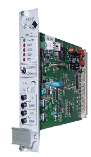
The DM-15 modem is a single card modem with a back termination card for 19" rack installation or the stand-alone enclosure.
The modem operates in Bell 202T mode using Frequency Shift Keying (FSK) and are designed for asynchronous or bit oriented data operations at 1200 baud.
The modem provides half-duplex communication on 2-wire private line circuits or full duplex communication on 4-wire private line circuits.
The I/O back termination card provides connectivity to the DC power supply, 1 x RS 232 DCE and VF communication channels. The back termination card is suitable for mounting options available.
The configuration of the modem cards is downloadable through the RS 232 port using the DM-15 utility.
The DM-15 modem is a Bell 202T Frequency Shift Keyed (FSK) modem designed for
asynchronous byte or bit oriented
communications up to 1200 Baud.
This modem provides half-duplex communications on 2-wire private line circuits or full duplex communication on 4-wire private line circuits.
Operation
The Bell 202T modem is designed for use in a single EuroCard 19'' sub-rack system. This rack can accommodate 17 Bell 202T modems as well as 2 redundant power supplies for the system.
The rear communications interface consists of one DB-9 female connector for serial connection to each modem module. The 2/4-wire interface is provided for on an RJ-11 4/4 connector.
Configuration
Configuration is achieved by means of the DB-9 (female) serial interface on the front panel of the modem using the user-friendly Windows based software configuration utility.
When a PC is plugged into this port, (and RTS is asserted) the modem will enter configuration mode automatically. Once the PC plug is removed, the modem will restart. This prevents the necessity to withdraw each modem from the rack for configuration.
This configuration utility runs under Windows 95™, Windows 98™, Windows NT™, Windows 2000™.
The software configuration utility allows the user to:
The following parameters are available for configuration using the software utility:
|
Technical Characteristics |
||
|
|
|
|
|
|
|
|
|
Number of Serial Ports |
1 Channel |
|
|
Type of Interface |
RS 232 CCITT V.28 |
|
|
Data Transfer Rate |
1200 Baud |
|
|
Flow Control |
RTS, CTS, DCD |
|
|
Type of Connection |
Standard 9 pin serial connection |
|
|
|
|
|
|
Number of channels |
1 or 2 Channels |
|
|
Isolation |
5 kV through matching transformer |
|
|
Termination |
600 Ohm, 10 kOhm ( high impedance) |
|
|
Transmitter output range |
- 4 to – 20 dBm |
|
|
Minimum output power |
-20 dBm |
|
|
Receiver Sensitivity |
Four ranges, 0 to -15dBm, -5 to -20dBm, -15 to -25 dBm, and -20 to -40dBm |
|
|
Test facilities |
4 x 2mm test jacks and line disconnect switches |
|
|
|
|
|
|
Input Range |
+12 Vdc and –12 Vdc |
|
|
Power Consumption |
50 mA +12 Vdc & 8 mA at –12Vdc |
|
|
|
|
|
|
Process Indications |
1 x Power On LED Indication |
|
|
|
4 x DCE Interface LED Indication for TXD, CTS, RXD, DCD |
|
|
|
|
|
|
Radiated Emission |
EN 55 022 Class A (formerly CISPR –022) |
|
|
|
|
|
|
Protection Class |
IP 00 (IP 20 in rack) |
|
|
Ambient temperature |
|
|
|
· = Continuous Operation |
-10° to +60° C |
|
|
· = Transportation and storage |
-40° to +70° C |
|
|
Relative Humidity |
95% |
|
|
|
|
|
|
Dimensions (W * H * D) |
5 hp x 3U (25.4 x 133.3 x 170 mm) |
|
|
Mass |
Approx. 160 grams |
|
|
|
||