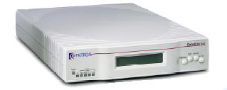
Kentrox Satellite 651 Single-port DSU/CSU
Please contact us 301-924-7400
Kentrox
Satellite 651 Single-port DSU/CSU
Kentrox Satellite 651 Single-port DSU/CSU
Please contact us
301-924-7400
Kentrox Satellite 651 Single-port DSU CSU
Description
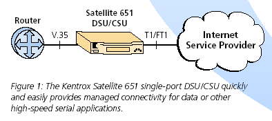
The Satellite™ 651 DSU/CSU is the ideal low cost access solution for T1 and FT1 networks. The unit ships with default settings for the most common confi gurations (ESF framing and B8ZS line coding), so it is as easy to set-up as it is to use. You can customize these settings and manage the unit locally via the front-panel LCD and push buttons. For even greater management capability, use the Satellite 651 in tandem with Kentrox DataSMART® DSU/CSUs. With a DataSMART at the central site, you can access the remote Satellite 651 via the ESF FDL link. You can change the unit’s configuration, collect full performance statistics, view system status, and generate loopbacks. An industry-standard V.35 data port provides connectivity to the widest range of customer premise equipment.
Features
• Connects router, video or any other serial
application
• Complete remote performance monitoring and diagnostics
• Integrated AC power supply
• Extensive loopbacks
• Low-cost remote offi ce access
• Remote management with any DataSMART DSU/CSU
• Local control with front panel LCD and LEDs
• Supports T1 / FT1 leased-line and Frame Relay services
• Five-year warrantyy
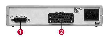
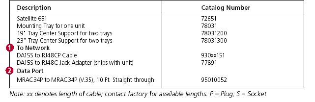
Ordering Information
Specifications
NETWORK INTERFACE
Line Rate: Internal or external clock; 1.544 Mb/s ± 50 bps.
When timing is derived from input signal:
1.544 Mb/s ± 200 bps
Output line rate follows input line rate
Line Code: AMI or B8ZS (B8ZS set as default)
Line Impedance: 100 ohms ±10 ohms at 772 kHz
100 ohms ± 20% over the frequency band
100 kHz to 1 MHz
Lightning Protection:
Lightning surges defi ned per FCC Part 68
shall not damage the unit
Framing Format: SF or ESF per ANSI T1.403-1989, and
TR-54016-1989; (ESF set as default)
Input Level : DS-1 from 0 dB to –27.5 dB
(0 dB set as default)
Input Jitter Tolerance:
Per TR 62411-1990 (p. 4.7.1)
Output Level: Per ANSI T1.403-1989
3.0 Volt peak ± 10% into 100 ohms at
output connector
Output Signal: Tolerant to impedance mismatches
Line Build Out: 0, 7.5, 15.0 selectable
Output Jitter: TR 62411-1990 (p. 4.7.3)
Jitter Transfer: DSU: TR 62411-1990 (p. 4.7.3)
Pulse Density: When enabled shall be > 12.5%
Mechanical: DA15 Plug (DB15 Male)
DATA PORT
Bit Rates: Nx56 kbps or Nx64 kbps (N-1…24)
Mechanical: 34-pin MRAC34S connector
Electrical Interface: V.35 compatible
Interface Type: DCE
DIAGNOSTICS
LEDs: Power/fail; T1; Data port transmit; Data
receive; Data port CTS; Data port RTS
Loop Tests: Local loopback; Data terminal loopback
T1 LOCAL LOOP DIAGNOSTICS
Loop Tests: Line loopback; Payload loopback
Data port loopback
Line Test Codes: QRS; 3-in-24; 1-in-8; All 1s; All 0s
Data Test Codes: 511; 2047
BERT Tester: Independent BERT on all test codes
MANAGEMENT
In-Band: Via ESF FDL
LCD: Front panel display of unit status
Front panel confi guration of unit
ENVIRONMENTAL
Storage Tempature: -20°C to 66°C (5% to 65% RH)
Operating Temp: 0°C to 50°C (5% to 90% RH, non-condensing)
PHYSICAL
Size with Feet: 1.7 inches by 7.75 inches by 11.5 inches
Size without Feet: 1.65 inches by 7.75 inches by 11.5 inches
Weight: Approximately 2.5 pounds
POWER
AC: 85 to 130 VAC, 47 to 63 Hz, 8W
REGULATORY
FCC Compliance: Part 68; Part 15, Class A
NRTL Listed: UL 1950, 3rd Edition
CSA: 22.2; No. 950
IC: CS-03
COMPATIBILITY
ANSI: T1.403-1995
AT&T: TR 54016-1989; TR 62411-1900
TR 54019A; PUB 43802
Bellcore: TR 194
WARRANTY
Hardware: 5 Years