FEATURES
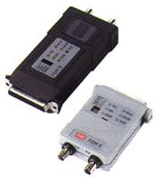
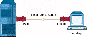
- The FOM-9, sync/async Short Range Modem, is used
for local data distribution, connecting full or half duplex, sync or async
terminals to computers over Single Mode or Multimode fiber optic cable.
FOM-9 operates at data rates of 32 to 128 kbps in sync mode or 9.6 to
115.2 kbps in async mode. FOM-9 operates at distances up to 16 km (10
miles) depending on the type of fiber optic cable.
- There are five available FOM-9 models:
- FOM-9/V.24/UP, unpowered,with V.24 interface*
- FOM-9/V.24, with V.24 interface
- FOM-9/V.35, with V.35 interface
- FOM-9/X.21, with X.21 interface
- FOM-9/530, with RS-530 interface
Each model has a 25-pin D-type connector for the DTE
interface. The V.35 interface is supplied with a 45 cm (17.7") cable, with
a 25-pin female connector on one side and a 34-pin male or female
connector on the other side. The X.21 interface is supplied with a 45 cm
(17.7") cable with a 25-pin male connector on one side, and a 15-pin X.21
female connector on the other side.
*FOM-9/V.24/UP is an unpowered ultra-miniature version of FOM-9.
- FOM-9 performs diagnostic loops in compliance with
ITU V.54 standard. Two V.54 loops are available: analog loop (V.54 Loop 3)
and remote digital loop (V.54 Loop 2). These loops are activated either by
a dip-switch or by the DTE interface Circuit 141 (Pin 18) and Circuit 140
(Pin 21). (Loopbacks in FOM-9/X.21 can only be activated via dipswitch.) A
proprietary local-digital loop is available and can be activated only by
the product's switches. This loop connects the local RD to the TD. A TEST
LED lights when any of the diagnostic loops is ON.
- FOM-9 includes a built-in V.52 standard BER tester
for testing link integrity. The internal BER tester is activated by a
switch on the top of the product. The BER tester checks the receive data
and turns on an ERROR LED when an error is detected.
- Asynchronous transmission is provided by internal
conversion from async to sync, in compliance with ITU V.22 bis standard.
Different async formats are switch selectable.
- In synchronous mode, transmit timing can be
provided by one of three user-selectable sources:
- Internal oscillator
- External clock
- Loopback clock derived from the receive signal.
- The modem's carrier can be strapped for either
continuous operation or for switched operation. In switched operation, the
carrier is controlled by the RTS signal and enables transfer of a control
signal end-to-end.
- FOM-9 incorporates all the advantages of a fiber
optic system:
- Lower attenuation than with copper wires;
attenuation is not related to frequency;
- EMI/RFI immunity which saves the cost of
expensive and heavy shielding and complex error checking routines;
- High data security: risk of eavesdropping is
minimized as fibers radiate negligible power; cost of data encryption is
reduced;
- Safety and electrical isolation: no spark hazard
and no ground-loop noise problems.
- FOM-9 includes six LEDs for indicating signal
status: RTS, TD, RD, CD, TST & ERR.
- FOM-9/V.24/UP's innovative circuitry design allows
operation without power supply, by using ultra-low power from the standard
RS-232/V.24/UP data and control signals. For proper operation, both data
and control signals must be connected, i.e. TD, RD, RTS and DTR.If the DTE
cannot provide enough power for normal operation of the unit, use
FOM-9/V.24.
- FOM-9/V.35, FOM-9/X.21, FOM-9/V.24 and FOM-9/530
include an external power jack for normal operation of the unit. An
additional external 9 VDC 300 mA wall mounted adapter should be ordered
separately and used to power the unit.
SPECIFICATIONS
- Synchronous or asynchronous
- Single Mode and Multimode supported
- Data rates up to 128 kbps sync and 115.2 kbps async
- V.54 diagnostics, including local and remote
loopbacks
- Built-in BERT in compliance with V.52
- Full or half duplex
- Controlled or continuous carrier
- Internal, external or receive clock
- Transmission range up to 16 km (10 miles) over
Single Mode fiber
- LED indicators
- V.24, V.35, X.21 or RS-530 interface options
- External, wall mounted power supply for all models
except FOM-9/V.24/UP
FOM-9/*/+
Synchronous/Asynchronous Short Range Fiber Optic Modem
FOM-9/V.24/UP/*/+
Synchronous/Asynchronous Short Range Fiber Optic Modem, Unpowered
| * |
Specify DTE interface:
V24/UP for unpowered V.24 interface, female connector
V24 for V.24 interface, female connector
V35 for V.35 interface, female connector
X21 for X.21 interface, female connector
530 for RS-530 interface, female connector |
| + |
Specify optical interface:
85ST for 850 nm Multimode ST connector
85SC for 850 nm Multimode SC connector
85FC for 850 nm Multimode FC-PC connector
13ST for 1300 nm Single Mode ST connector
13SC for 1300 nm Single Mode SC connector
13FC for 1300 nm Single Mode FC-PC connector |
ORDERING
FOM-9/115/V24/ST13
FOM-9/115/V24/ST85
FOM-9/115/V35/ST85
FOM-9/230/530/ST13
FOM-9/230/530/ST85
FOM-9/V24/ST85
FOM-9/V24/UP/ST13
FOM-9/V24/UP/ST85
APPLICATION
|