- T1 or Fractional T1 access unit
- Supports one data port with selectable sync data
rates: n x 56, n x 64 kbps
- Optional sub-T1 drop & insert port for PABX
connectivity
- Single slot supports the MEGAPLEX I/O modules HS-Q
or VC-6
- Failure immune sub-T1 link ensuring uninterrupted
service (G.703 only)
- Data interfaces: V.35, RS-530, V.36/RS-449 or X.21
- Optional high performance built-in Ethernet
bridge/router
- SNMP agent
- Management:
- Out-of-band via V.24 supervisory port or Ethernet
management port
- Inband via TS 0 or dedicated timeslot
- Dial-in option for remote out-of-band management
- Dial-out for alarm report
- T1 main link available with or without LTU
- Optional fiber optic main link with the following
interfaces:
- 850 nm LED for multimode
- 1300 nm LED for single mode
- 1300 nm laser for single mode
- 1550 nm laser for extended range over single mode
- Framing format (main link and sub-T1 port): 2 or 16
frames per multiframe, with or without CRC-4
- Zero suppression (main link and sub-T1 port): HDB3
- T1 interface complies with: ITU G.703, G.704,
G.706, G.732, G.823
- Enhanced diagnostics include:
- User activated local and remote loopbacks
- Integrated BER tester
- Fractional T1 in-band loop
- Stores 24 hours of T1 network performance
monitoring and last 100 alarms
- Relay activation upon alarm event
- Alarm mask configurable for any alarm
BASIC UNIT
- The basic unit includes power supply, T1 link and
one data port.
- The T1 interface is compatible with virtually all
carrier provided T1 services and meets ITU recommendations G.703, G.704,
G.706 and G.732. The T1 interface supports either 2 or 16 frames per
multiframe, with or without CRC-4. Zero suppression over the line is HDB3.
The integral LTU (optional) ensures a range of up to 2 km.
- FCD-T1M can be ordered with a fiber optic link,
which eliminates the need for an external fiber optic modem. The fiber
optic link provides a secure link in hazardous or hostile environments. It
complies with ITU standards G.921 and G.956.
- Four fiber optic interfaces are available:
- 850 nm LED for use over multimode fiber at
distances up to 5 km (3 miles)
- 1300 nm LED for use over single mode fiber at
distances up to 47 km (29 miles)
- 1300 nm laser diode for use over single mode
fiber at distances up to 62 km (38 miles)
- 1550 nm laser diode for use over single mode
fiber for extended range up to 100 km (62 miles).
- Timeslot assignment is programmable, allowing data
from each data port and from the sub-T1 port to be placed into timeslots
consecutively. FCD-T1M also provides additional flexibility, by giving
full user control over the data ports timeslot allocation without
restrictions.
- Multiple clock source selection ensures maximum
flexibility for supporting different applications. The T1 main link may be
clocked from the recovered receive clock, from an internal oscillator,
from one of the data ports or from the sub-T1 port.
- Bypassing the sub-T1 port to the main link
(non-fiber optic), ensures uninterrupted service to the sub-T1 port and
provides immunity to hardware and power failure.
- FCD-T1M is available as a standalone unit. A rack
mount adapter kit enables installation of the unit in a 19" rack.
USER INTERFACE
- The following data port interfaces can be ordered:
V.35, RS-530, V.36/RS-449 or X.21. The ports can operate in the following
clock modes:
- Invert data sampling is done using an invert clock.
- The optional built-in Ethernet bridge is a high
performance remote, self-learning bridge. It is ideal as a LAN extender or
segmenter over T1 link applications. The LAN table stores up to 10,000
addresses and is automatically updated. Filtering and forwarding is
performed at the maximum theoretical rate of 15,000 pps (wire speed) and
the buffer can hold 256 frames with a throughput latency of 1 frame.
Filtering can be disabled for extender or segmenter applications. The
Ethernet port is available with 10BaseT (UTP) which operates in full
duplex.
- The optional built-in Ethernet router is a high
performance remote IP router. It is ideal as a LAN extender or segmenter
over bit-stream type infrastructures. The router works by taking each
Ethernet frame from the LAN and according to its destination forwards the
packets to the IP net on the Ethernet LAN or to the WAN. The Ethernet port
is available in 10BaseT (UTP) which operates in full duplex mode.
- The optional sub-T1 port can be configured to work
without CRC-4, while the T1 main link is working with CRC-4. Thus,
connection of T1 equipment not supporting CRC-4, over an T1 network that
is working with CRC-4 is available.
MANAGEMENT & MAINTENANCE
- Setup, control and monitoring of status and
diagnostics information can be activated via:
- ASCII terminal connected to the async control
port command line interpreter
- SNMP management connected to the async control
port.
- FCD-T1M has an internal SNMP agent and can be
controlled by any generic SNMP station or by the RADview SNMP network
management application.
- FCD-T1M supports dial-in, dial-out modem
connections. These connections can be used for remote out-of-band
configuration, monitoring and for sending callout alarm messages using
serial V.24 SLIP, PPP or Ethernet ports.
- In-band management can be performed by using the
spare bits (Sa bits) on timeslot 0 or by using a dedicated timeslot using
standard protocols, Frame Relay (RFC 1490), PPP and standard RIP2 routing.
This allows setup, monitoring and diagnostics of the remote unit. In-band
access by using spare bits on timeslot 0 is possible only if those bits
are passed transparently end-to-end.
- Maintenance capabilities include user activated
local and remote loopbacks at the T1 main link, sub-T1 and data ports. The
user can activate a BER test for each data or sub-T1 port individually.
Each data or sub-T1 port responds to an ANSI FT1 RDL (T1E1.2/93-003)
in-band loop code, generated from the remote FCD-T1M or DXC in a specific
bundle of timeslots allocated only to that port.
- When operating with CRC-4, T1 network statistics
are stored in memory according to RFC-1406. The statistic information may
be retrieved locally through the control port.
ORDERING
FCD-T1M/S1/48/UTP/V35/FC13
FCD-T1M/S1/AC/U/ETU/R
FCD-T1M/S1/AC/U/V35
APPLICATION
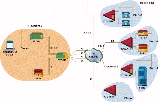
Figure1 - Extended Ethernet Management over
T1/E1 Network
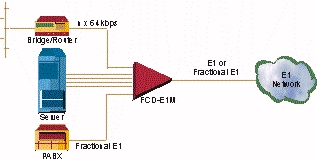
Figure 2 - Connection of LAN Traffic together
with PABX Traffic to T1/E1 Network
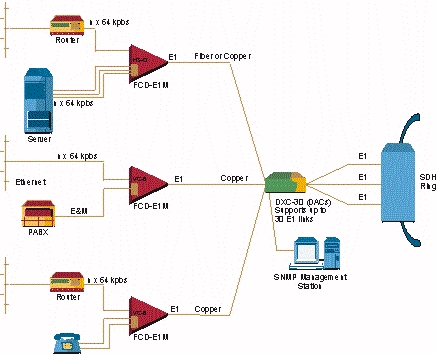
Figure 3 - SDH Access Solution for
Multiple Remote Sites
|