FEATURES
- The ASMi-50, Synchronous Short Range Modem,
operates in full duplex over 2 and 4-wire lines. Operation over 4-wire
link provides 10% improvement in the maximum range of the modem. Data
rates are user selectable between 64 kbps and 1152 kbps.
- The modem employs MS-DSL 2B1Q technology to extend
the transmission range (see Table 1 and Table 2) and provide efficient
transmission, even over poor quality lines.
- The modem uses an out-of-band management channel
for controlling and monitoring the remote unit. Both data and management
are transmitted over the same wires, simultaneously.
- Menu-driven software, activated from the front
panel, allows soft-select monitoring and adjusting of local and remote
units. The software menus allow the user to monitor and control the
following parameters:
- Baud rate (when set to Internal or Receive mode)
- Clock source
- Output transmit level
- Loop activation
- Internal BER tester activation
- LED status of local and remote units
- Setting both local and remote units to default settings
- Real time monitoring of link status
- Real time alert of fault conditions
- Real time signal quality monitoring.
- The transmit clock is derived from three different
selectable sources:
- Internally from a built-in oscillator
- Recovered from the received signal
- From the digital interface (for tail-end applications).
- When set to external mode, ASMi-50 automatically
detects the clock rate coming from the digital interface and sets the
remote unit to the same rate. When the digital interface rate is changed,
both local and remote units follow the new rate and synchronize
accordingly.
- ASMi-50 supports a wide range of digital
interfaces: V.24 (64 kbps), V.35, X.21, RS-530, V.36/RS-449 and G.703
Codirectional (64 kbps). In addition, an Ethernet/802.3 bridging option
enables direct connections of an Ethernet LAN to both sides of the ASMi-50
link, saving the need for an external bridge.
- The ASMi-50 system configuration is stored in
non-volatile memory, minimizing system down-time when power is down or
when a faulty remote unit is replaced.
- The out-of-band management channel provides real
time alerts for:
- Disconnection of the digital data transmission
- Disconnection of the management channel
- Remote modem failure
- Loop activation.
- Real time indication of system status is provided
on the front panel's LCD for the local and remote modems.
- ASMi-50 is available as a standalone unit in both
ASMi-50/M "Master" and ASMi-50/S "Slave" versions. The master version has
a front panel LCD and control switches. The slave unit has a blank panel,
which prevents unauthorized changes to link parameters. ASMi-50 is also
available as a card for central solutions:
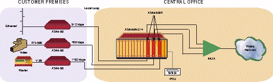
- ASMi-50/R - card for the ASM-MN-214 19" modem rack
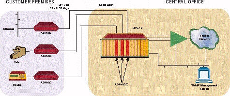
- ASMi-50C - card for the LRS-12 19" modem rack with central SNMP
management.
- Management of the local and remote modems in the
ASMi-50/S and ASMi-50/R card versions is carried out via a standalone
Portable Control Unit (PCU) through a special 20-pin connector on the
modem front panel. The PCU is ordered separately (see Ordering).
- The ASMi-50C card for the LRS-12 rack can be
managed from an ASCII terminal or via an SNMP UNIX station connected to
the rack. RADview, an SNMP application, is available for managing the
ASMi-50C cards and other RAD products. RADview enables management of a
large number of links, system infrastructure, and presentation of
statistical information on link availability. It is a user friendly system
providing a graphical presentation of all network elements.
- Diagnostic features include different loop
activations, as well as an internal BER tester. The loops available are:
- Local analog loopback
- Local digital loopback
- Remote digital loopback
- Remote analog loopback.
The loops can be activated from the front panel, PCU (Portable Control
Unit) or from the digital interfaces that support loop activation signals
SPECIFICATIONS
- Extends range of data transmission over 2 and
4-wire lines up to 22 km
- Wide range of data rates between 64 and 1152 kbps
- MS-DSL 2B1Q technology for extended range and
improved performance
- Variety of digital interfaces:
- V.24 (64 kbps)
- V.35
- X.21
- RS-530
- V.36/RS-449
- Ethernet (built-in bridge)
- G.703 Codirectional (64 kbps)
- Automatic rate detection in external clock mode for
tail-end applications
- Configuration and monitoring of local and remote
units from front panel
- Card version available for ASM-MN-214 19" modem
rack and LRS-12 19" modem rack with central SNMP management
ASMi-50/M/*/#
Extended Range Modem (Master), stand-alone unit
ASMi-50/S/*/#
Extended Range Modem (Slave), stand-alone unit
ASMi-50/R/#
Card for the ASM-MN-214 19" rack
ASMi-50CF/#
Card for the LRS-12 19" rack - ETSI version
ASMi-50CB/#
Card for the LRS-12 19" rack - ANSI version
CIA/&
Adapter for 25-pin, D-type to V.35 or X.21 connector for ASM-MN-214 racks
for two adjacent cards
| * |
Specify power supply:
115 for 115 VAC
230 for 230 VAC
48 for -48 VDC
24 for 24 VDC |
| # |
Specify digital interface:
V24 for V.24
V35 for V.35
V35A for V.35 with DB-25 connector
V36 for V.36/RS-449
530 for RS-530
X21 for X.21
703/TB for G.703 Codirectional with terminal block (standalone
option)
703/RJ for G.703 Codirectional with RJ-45 connector (standalone
option)
703 for G.703 Codirectional with RJ-45 connection (ASM-MN-214 and
LRS-12 versions)
UTP for built-in Ethernet/802.3 bridge with RJ-45 connector BNC
for built-in Ethernet/802.3 bridge with BNC connector (available in
standalone only)
|
| & |
Specify connector:
V35 for V.35 connector
X21 for X.21 connector |
PCU
Portable Control Unit with protective casing
ORDERING INFO
|
ASMI-50-1/CB/V35 |
|
ASMI-50-1/CDB/UTP |
|
ASMI-50-1/CDB/V35 |
|
ASMI-50-1/M/115/530 |
|
ASMI-50-1/M/115/UTP |
|
ASMI-50-1/M/115/UTP/Q |
|
ASMI-50-1/M/115/V35 |
|
ASMI-50-1/M/230/UTP |
|
ASMI-50-1/M/230/V35 |
|
ASMI-50-1/R/UTP |
|
ASMI-50-1/S/115/UTP |
|
ASMI-50-1/S/115/UTP/Q |
|
ASMI-50-1/S/115/V35 |
|
ASMI-50-1/S/230/UTP |
|
ASMI-50-1/S/230/V35 |
APPLICATION
Table 1. Typical Data Rates for 2-wire
Lines
| Data Rate |
19 AWG |
22 AWG |
24 AWG |
26 AWG |
| (kbps) |
km |
miles |
km |
miles |
km |
miles |
km |
miles |
| 1152 |
10.5 |
6.5 |
7.5 |
4.5 |
6.0 |
3.5 |
4.5 |
2.8 |
| 1024 |
11.0 |
7.5 |
8.0 |
5.0 |
6.5 |
4.0 |
5.0 |
3.0 |
| 896-960 |
12.0 |
7.5 |
9.0 |
5.5 |
7.0 |
4.2 |
5.5 |
3.2 |
| 768 |
12.5 |
8.0 |
9.5 |
6.0 |
7.5 |
4.5 |
5.5 |
3.2 |
| 576-640 |
13.5 |
8.0 |
9.5 |
6.0 |
7.5 |
4.5 |
5.5 |
3.0 |
| 512 |
14.5 |
9.0 |
10.5 |
6.5 |
8.5 |
5.0 |
6.0 |
3.5 |
| 384-448 |
16.0 |
10.0 |
11.5 |
7.0 |
9.0 |
5.5 |
6.5 |
4.0 |
| 64-320 |
18.5 |
11.5 |
13.0 |
8.0 |
9.5 |
6.0 |
6.5 |
4.0 |
Table 2. Typical Data Rates for 4-wire
Lines
| Data Rate |
19 AWG |
22 AWG |
24 AWG |
26 AWG |
| (kbps) |
km |
miles |
km |
miles |
km |
miles |
km |
miles |
| 1152 |
11.0 |
7.0 |
8.0 |
4.2 |
6.5 |
3.8 |
5.0 |
3.0 |
| 1024 |
12.0 |
7.5 |
8.5 |
5.2 |
7.0 |
4.2 |
5.5 |
3.2 |
| 768-960 |
12.5 |
8.0 |
9.5 |
6.0 |
8.0 |
4.2 |
6.0 |
3.5 |
| 640 |
13.5 |
8.5 |
10.5 |
6.5 |
8.5 |
5.2 |
6.5 |
3.8 |
| 576 |
15.5 |
9.8 |
11.5 |
7.2 |
9.0 |
5.5 |
6.8 |
4.0 |
| 448-512 |
16.5 |
10.2 |
12.0 |
7.5 |
9.5 |
6.0 |
7.0 |
4.2 |
| 64-384 |
22.0 |
13.5 |
15.0 |
9.0 |
11.0 |
7.0 |
7.5 |
4.5 |
|