Features
- The ASMi-24, Sync Short Range Modem with Remote
Management, operates full or half duplex over twisted pair, 4-wire
unconditioned lines. It has a transmission range of up to 10 km (6 miles)
and operates at user-selectable rates from 48 to 144 kbps.
- The modem uses PR4 line code (Partial Response
Class IV), which provides immunity to background noise, eliminates normal
line distortion, and enables efficient transmission over 4-wire twisted
pair cables. Transmit timing is either provided internally, or recovered
from the received signal (user-selectable). Alternatively, the transmit
timing can be derived externally from the digital interface, enabling
tail-end applications. The carrier may be continuous or controlled by RTS
for passing control signals end-to-end (user-selectable).
- The modem's front panel provides real-time
indication on application status.
- The modem uses an out-of-band management channel
for controlling and monitoring the remote unit. Both data and management
are transmitted over the same wires, simultaneously.
- Menu-driven software allows soft-select monitoring
and adjustment of local and remote unit parameters via the control keys
and LCD.
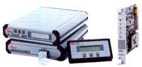
- ASMi-24 is available as a standalone unit in both
ASMi-24/M "Master" and ASMi-24/S "Slave" versions. The Master version has
a front panel LCD and control switches. The Slave unit has a blank panel,
which prevents unauthorized changes to link parameters. ASMi-24 is also
available as a card for central solutions:
- ASMi-24/R - card for the ASM-MN-214 19" rack
- ASMi-24C - card for the LRS-12 19" rack with central SNMP management.
- Management of the local and remote modems for the
ASMi-24/S and ASMi-24/R card versions is carried out via a standalone
Portable Control Unit (PCU), through a special 20-pin connector on the
modem front panel. The PCU is ordered separately (see Ordering).
- All management functions, except for clock source
and clock rate, can be initiated from the Slave unit PCU. The PCU,
provided with a protective casing, can be stored in a technician's tool
kit.
- The following Master and Slave modem parameters are
monitored and controlled via the front panel:
- Baud rate
- RTS, CTS delay
- Carrier detection
- Clock source
- Carrier mode
- V.54 loops enable
- Built-in system configuration-saver in the event of power failure
- TX LEVEL
- RX SENSE.
- The ASMi-24C card for the LRS-12 rack can be
managed from an ASCII terminal or via an SNMP UNIX station connected to
the rack. RADview, an SNMP application, is available for managing ASMi-24C
cards and other RAD products. RADview enables management of a large number
of links, system infrastructure, and presentation of statistical
information on link availability. It is a user friendly system, utilizing
a graphical presentation of all network elements.
- ASMi-24 features a built-in BERT, which complies
with the V.52 standard, and can be activated and monitored via the front
panel. This feature enables complete testing of the line.
- Tests which can be initiated via the Master front
panel include activating local and remote loopbacks, and activating local
BERT. Real-time link errors are displayed on the ERR LED, and BER RESULTS
on the LCD screen.
- Real time alerts indicated via the Master front
panel include disconnection of the modem link, remote modem power failure,
and carrier loss. Remote and local LED indicators can be displayed on the
front panel of the Master unit.
- The remote modem performs a Far Analog Loop
self-check and displays real time errors on the LOCAL ERR LED, and BER
RESULTS on the LCD screen.
- Diagnostics of the modem link include real error
rate display and simultaneous activation of BERTs on the local and the
remote units.
- Among many field interchangeable interfaces,
ASMi-24 can be ordered with a built-in Ethernet (10BaseT) bridge
interface. This option can be used for LAN to LAN connectivity over 4-wire
extended range, using only a pair of ASMi-24 modems.
Specifications
- Extended range, baseband modem - up to 10 km (6
miles) at 64 kbps
- Full management of local and remote modems via
front panel
- Remote out-of-band management for all line
conditions
- Real-time alarm indication for local and remote
units
- Selectable data rates:
48 kbps up to 144 kbps
- Fully compatible with ASM-24
- Full or half duplex on 4-wire lines
- V.54 and built-in BER tester diagnostics
- Carrier control option
- Supports digital interfaces: V.24/RS-232, V.35,
X.21, V.36/RS-449, RS-530 or G.703 Codirectional
- A special built-in Ethernet bridge for LAN to LAN
connectivity
- Card version available for ASM-MN-214 19" rack and
LRS-12 19" rack with central SNMP management
ASMi-24SA/*/#/+
Short Range Modem, standalone unit with internal power supply
ASMi-24R/#
Short Range Modem card for the ASM-MN-214 19" rack
ASM-MN-214/*/&
19" rack for 14 modem cards
ASMi-24CF/#
Short Range Modem Card for the ETSI LRS-12 rack
ASMi-24CB/#
Short Range Modem Card for the ANSI LRS-12 rack
| * |
Specify standalone and rack main power supply:
115 VAC for 115 VAC
230 VAC for 230 VAC
48 for -48 VDC |
| # |
Specify digital interface:
V24 for V.24/RS-232
V35 for V.35
V36 for V.36/RS-449
530 for RS-530 (V.11/RS-422 on 25-pin)
X21 for X.21
G.703/TB for G.703 Codirectional (64 kbps) with terminal block
connector
G.703/RJ for G.703 Codirectional (64 kbps) with RJ-45 connector
G.703 for G.703 Codirectional (64 kbps) in rack card version
UTP for built-in Ethernet/802.3 bridge with RJ-45 connector
BNC for built-in Ethernet/802.3 bridge with BNC connector |
Note: When using V.35 or X.21 interfaces, the CIA
adapter is required.
| + |
Specify Master or Slave:
M for Master
S for Slave |
| & |
Specify redundant power supply
for rack: (same options as main power supply). |
ACCESSORIES
PCU
Portable Control Unit with protective casing
CIA/&
Connector Interface Adapter for the ASM-MN-214 19" rack
| & |
Specify CIA connector option:
V35/1 for adapting one modem card's 25-pin connector into one
V.35, 34-pin connector
X21 for adapting two adjacent modem cards' 25-pin connectors to
two X.21, 15-pin connectors |
ORDERING INFO
ASMI-24/CB/530
ASMI-24/CB/V35
ASMI-24/M/115/530
ASMI-24/M/115/V24
ASMI-24/M/115/V35
ASMI-24/M/230/G703T
ASMI-24/M/230/V35
ASMI-24/S/115/530
ASMI-24/S/115/V24
ASMI-24/S/115/V35
APPLICATION
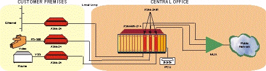
Figure 1. Access for a Small Office in a
Multiprotocol Environment
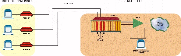
Figure 2. Central Site Application with SNMP Management
|