RAD AMC-102
High Speed Media Converter and Repeater
Call us for
Pre-sales and discount pricing
301-924-7400
Support
|
Features Modular media converter and repeater
|
AMC-101 Applications
1)
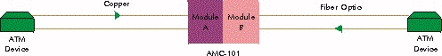
Figure 1
- Conversion between Differnet Media
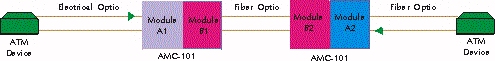
Figure 2
- Repeater Application
(Using only retimed modules for protocols running at 155, 100 or 51 Mbps)
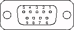
Figure 7. Connector Pin Assignment
Table 1. Connector Pin Assignment Table
PIN TYPE ALARM TYPE COM OK FAIL RED 9 4 5 YELLOW 3 8 7 CONFIG 6 2 1
Table 2. Bridging Modules
Module Name Protocols Supported Cable Type Connector Type Range Impedance 10BT/B Ethernet UTP Cat 5 Shielded RJ-45 100m 100 100BT/B Fast Ethernet UTP Cat 5 Shielded RJ-45 80m 100 100BT/R Fast Ethernet UTP Cat 5 Shielded RJ-45 80m 100 * Remote Ethernet bridge module
** Remote Fast Ethernet bridge module
*** Media converter for Fast Ethernet (Tx to Fx)
Table 3. Optical Module Characteristics
Module Name Protocols Supported Fiber Type (Wavelength) Connector Type Typical Distance Dynamic Range Optical Power (typical) Sensitivity MM/ST/85* Token Ring, Ethernet only, FDDI, Fast Ethernet 62.5/125 (850 nm) ST 2 km / 1.2 mile 18 dB -18 dBm -30 dBm MM/SC/13** TAXI, FDDI, Fast Ethernet, STS-1, STS-3c/STM-1 62.5/125 (1300 nm) SC 2 km / 1.2 mile 17 dB -18 dBm -31 dBm MM/ST/13** TAXI, FDDI, Fast Ethernet, STS-1, STS-3c/STM-1 62.5/125 (1300 nm) ST 2 km / 1.2 mile 17 dB -18 dBm -31 dBm SF1/FC*** TAXI, FDDI, Fast Ethernet, STS-1, STS-3c/STM-1 9/125 Transmit 1300 nm Receive 1550 nm FC-PC (Single Strand) 40 km / 25 mile 28 dB -12 dBm -29 dBm SF2/FC*** TAXI, FDDI, Fast Ethernet, STS-1, STS-3c/STM-1 9/125 Transmit 1550 nm Receive 1300 nm FC-PC (Single Strand) 40 km / 25 mile 28 dB -12 dBm -29 dBm SF1/ST*** TAXI, FDDI, Fast Ethernet, STS-1, STS-3c/STM-1 9/125 Transmit 1300 nm Receive 1550 nm ST (Single Strand) 40 km / 25 mile 28 dB -12 dBm -29 dBm SF2/ST*** TAXI, FDDI, Fast Ethernet, STS-1, STS-3c/STM-1 9/125 Transmit 1550 nm Receive 1300 nm ST (Single Strand) 40 km / 25 mile 28 dB -12 dBm -29 dBm SM/FC/13** TAXI, FDDI, Fast Ethernet, STS-1, STS-3c/STM-1 9/125 (1300 nm) FC-PC 25 km / 16 mile 30 dB -18 dBm -31 dBm SM/FC/13L** TAXI, FDDI, Fast Ethernet, STS-1, STS-3c/STM-1 9/125 (1300 nm) FC-PC 40 km / 25 mile 30 dB -10 dBm -31 dBm SM/FC/13LH** (LASER) TAXI, FDDI, Fast Ethernet, STS-1, STS-3c/STM-1 9/125 (1300 nm) FC-PC 60 km / 37 mile 33 dB -2 dBm -34 dBm SM/FC/15LH** (LASER) TAXI, FDDI, Fast Ethernet, STS-1, STS-3c/STM-1 9/125 (1550 nm) FC-PC 110 km / 68 mile 33 dB -1 dBm -34 dBm SM/SC/13L** (LASER) TAXI, FDDI, Fast Ethernet, STS-1, STS-3c/STM-1 9/125 (1300 nm) SC 40 km / 25 mile 30 dB -10 dBm -31 dBm SM/ST/13** TAXI, FDDI, Fast Ethernet, STS-1, STS-3c/STM-1 9/125 (1300 nm) ST 25 km / 16 mile 30 dB -18 dBm -31 dBm SM/ST/13L** (LASER) TAXI, FDDI, Fast Ethernet, STS-1, STS-3c/STM-1 9/125 (1300 nm) ST 40 km / 25 mile 30 dB -10 dBm -31 dBm SM/ST/13LH** (LASER) TAXI, FDDI, Fast Ethernet, STS-1, STS-3c/STM-1 9/125 (1300 nm) ST 60 km / 37 mile 33 dB -2 dBm -34 dBm SM/ST/15L** (LASER) TAXI, FDDI, Fast Ethernet, STS-1, STS-3c/STM-1 9/125 (1550 nm) ST 50 km / 31 mile 30 dB -10 dBm -31 dBm SM/ST/15LH** (LASER) TAXI, FDDI, Fast Ethernet, STS-1, STS-3c/STM-1 9/125 (1550 nm) ST 110 km / 68 mile 33 dB -1 dBm -34 dBm * Transparent only
** Data rates are switch selectable from the front panel
*** Retimed only
Note: Typical distances based on attenuation of 0.4 dB/km for 1300 nm modules and 0.25 dB/km for 1550 nm modules
Table 4. Electrical (Copper) Module Characteristics
Module Name Protocols Supported Cable Type Connector Type Range Impedance UTP/155* STS-3c UTP Cat 5 Shielded RJ-45 100m 100 STP/155 * STS-3c STP Type 1 DB-9 100m 150 UTP/100* FDDI UTP Cat 5 Shielded RJ-45 100m 100 CX/BNC/155** STS-3C, STM-1 Coax BNC 12.7 dB 75 CX/DIN/155** STS-3C, STM-1 Coax DIN 47295 1.6/5.6 Coaxial connector 12.7 dB 75 * 50m in transparent module
** At 78 MHz, according to square rood of frequency law; 150m is attainable when using RG-59 B/UFor discount pricing on RAD Data Communications
email us at sales@data-connect.com
or call 301-924-7400