FIBER OPTICS |
a Tutorial
Although fiber
optic cable is still more expensive than other types of cable, it's favored for
today's high-speed data communications because it eliminates the problems of
twisted-pair cable, such as near-end crosstalk (NEXT), electromagnetic
interference (EIVII), and security breaches.
• SPEED: Fiber optic networks operate at high
speeds - up into the gigabits
• BANDWIDTH: large carrying capacity
• DISTANCE: Signals can be transmitted further
without needing to be "refreshed" or strengthened.
• RESISTANCE: Greater resistance to electromagnetic
noise such as radios, motors or other nearby cables.
• MAINTENANCE: Fiber optic cables costs much less to
maintain.
There are three types of fiber optic cable: single mode, multimode and plastic optical fiber (POF).
Single Mode cable is a single stand of glass fiber with a diameter of 8.3 to 10 microns. (One micron is 1/250th the width of a human hair.)
Multimode cable is made of multiple strands of glass fibers, with a combined diameter in the 50-to-100 micron range. Each fiber in a multimode cable is capable of carrying a different signal independent from those on the other fibers in the cable bundle. POF is a newer plastic-based cable which promises performance similar to single mode cable, but at a lower cost.
While fiber optic cable itself is cheaper than an equivalent length of copper cable, fiber optic cable connectors and the equipment needed to install them are more expensive than their copper counterparts.
Fiber optic cable functions as a "light guide," guiding the light introduced at one end of the cable through to the other end. The light source can either be a light-emitting diode (LED)) or a laser.
The light source is pulsed on and off, and a light-sensitive receiver on the other end of the cable converts the pulses back into the digital ones and zeros of the original signal.
Even laser light shining through a fiber optic cable is subject to loss of strength, primarily through dispersion and scattering of the light, within the cable itself. The faster the laser fluctuates, the greater the risk of dispersion. Light strengtheners, called repeaters, may be necessary to refresh the signal in certain applications.
Fiber
by John MacChesney - Fellow at Bell Laboratories, Lucent Technologies
Some 10 billion digital bits can be transmitted per second along an optical fiber link in a commercial network, enough to carry tens of thousands of telephone calls. Hair-thin fibers consist of two concentric layers of high-purity silica glass the core and the cladding, which are enclosed by a protective sheath. Light rays modulated into digital pulses with a laser or a light-emitting diode move along the core without penetrating the cladding.
The light stays confined to the core because the cladding has a lower refractive index—a measure of its ability to bend light. Refinements in optical fibers, along with the development of new lasers and diodes, may one day allow commercial fiber-optic networks to carry trillions of bits of data per second.
Total internal refection confines light within optical fibers (similar to looking down a mirror made in the shape of a long paper towel tube). Because the cladding has a lower refractive index, light rays reflect back into the core if they encounter the cladding at a shallow angle (red lines). A ray that exceeds a certain "critical" angle escapes from the fiber (yellow line).
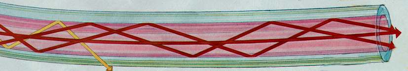
STEP-INDEX MULTIMODE FIBER has a large core, up to 100 microns in diameter. As a result, some of the light rays that make up the digital pulse may travel a direct route, whereas others zigzag as they bounce off the cladding. These alternative pathways cause the different groupings of light rays, referred to as modes, to arrive separately at a receiving point. The pulse, an aggregate of different modes, begins to spread out, losing its well-defined shape. The need to leave spacing between pulses to prevent overlapping limits bandwidth that is, the amount of information that can be sent. Consequently, this type of fiber is best suited for transmission over short distances, in an endoscope, for instance.
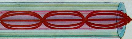
GRADED-INDEX MULTIMODE FIBER contains a core in which the refractive index diminishes gradually from the center axis out toward the cladding. The higher refractive index at the center makes the light rays moving down the axis advance more slowly than those near the cladding. Also, rather than zig-zagging off the cladding, light in the core curves helically because of the graded index, reducing its travel distance. The shortened path and the higher speed allow light at the periphery to arrive at a receiver at about the same time as the slow but straight rays in the core axis. The result: a digital pulse suffers less dispersion. These fibers often become the physical medium for local-area networks
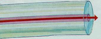
SINGLE-MODE FIBER has a narrow core (eight microns or less), and the index of refraction between the core and the cladding changes less than it does for multimode fibers. Light thus travels parallel to the axis, creating little pulse dispersion. Telephone and cable television networks install millions of kilometers of this fiber every year.
Fiber
Cable over view by Black Box
Over the past
few years, fiber optic cable has become more affordable. It's now used for
dozens of applications that require complete immunity to electrical
interference. Fiber is ideal for high data-rate systems such as FDDI,
multimedia, ATM, or any other network that requires the transfer of large,
time-consuming data files.
Other
advantages of fiber optic cable over copper include:
?
Greater distance-You can run fiber as far as several kilometers. ? Low
attenuation-The light signals meet little resistance, so data can travel
farther.
Single-mode or
multimode?
Single-mode
fiber gives you a higher transmission rate and up to 50 times more distance than
multimode, but it also costs more. Single-mode fiber has a much smaller core
than multimode fiber-typically 5 to 10 microns. Only a single lightwave can be
transmitted at a given time. The small core and single lightwave virtually
eliminate any distortion that could result from overlapping light pulses,
providing the least signal attenuation and the highest transmission speeds of
any fiber cable type.
Multimode fiber
gives you high bandwidth at high speeds over long distances. Lightwaves are
dispersed into numerous paths, or modes, as they travel through the cable's
core. Typical multimode fiber core diameters are 50, 62.5, and 100 micrometers.
However, in long cable runs (greater than 3000 feet [914.4 ml), multiple paths
of light can cause signal distortion at the receiving end, resulting in an
unclear and incomplete data transmission.
Testing and
certifying fiber optic cable.
?
Attenuation (or decibel loss)-Measured in dB/km, this is the decrease of signal
strength as it travels through the fiber optic cable. ? Return loss-The amount
of light reflected from the far end of the cable back to the source. The lower
the number, the better. For example, a reading of -60 dB is better than -20 dB.
? Graded
refractive index-Measures how much light is sent down the fiber. This is
commonly measured at wavelengths of 850 and 1300 nanometers. Compared to other
operating frequencies, these two ranges yield the lowest intrinsic power loss.
(NOTE This is valid for multimode fiber only.)
? Propagation
delay-This is the time it takes a signal to travel from one point to another
over a transmission channel.
? Time-domain
reflectometry (TDR)-Transmits high-frequency pulses onto a cable so you can
examine the reflections along the cable and isolate faults.
There are many
fiber optic testers on the market today. Basic fiber optic testers function by
shining a light down one end of the cable. At the other end, there's a receiver
calibrated to the strength of the light source. With this test, you can measure
how much light is going to the other end of the cable. Generally, these testers
give you the results in decibels (dB) lost, which you then compare to the loss
budget. If the measured loss is less than the number calculated by your loss
budget, your installation is good.
Newer fiber
optic testers have a broad range of capabilities. They can test both 850- and
1300-nm signals at the same time and can even check your Gable for compliance
with specific standards.
When to choose
fiber optic.
Although fiber
optic cable is still more expensive than other types of cable, it's favored for
today's high-speed data communications because it eliminates the problems of
twisted-pair cable, such as near-end crosstalk (NEXT), electromagnetic
interference (EIVII), and security breaches.
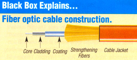
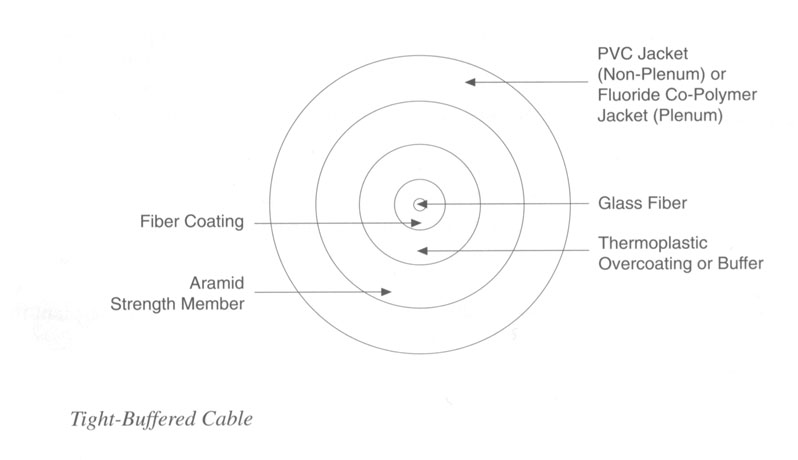
Fiber optic cable consists of a core, cladding, coating, strengthening fibers, and cable jacket (see above).
Core -This is the
physical medium that transports optical data signals from an attached light
source to a receiving device. The core is a single continuous strand of glass or
plastic that's measured (in microns) by the size of its outer diameter. The
larger the core, the more light the cable can carry. All fiber optic cable is
sized according to its core diameter. The three sizes most commonly available
are 50-, 62.5-, and 1 00-micron Gable.
Cladding -This is a thin layer that surrounds the fiber core and
serves as a boundary that contains the light waves and causes the refraction,
enabling data to travel throughout the length of the fiber segment.
Coating
-This is a layer of plastic that surrounds the core and cladding to reinforce
the fiber core, help absorb shocks, and provide extra protection against
excessive cable bends. These buffer coatings are measured in microns (p) and can
range from 250 p to 900 p.
Strengthening
fibers -These components help protect the core against crushing
forces and excessive tension during installation. The materials can range from
Kevlat4 to wire strands to gel-filled sleeves.
Cable jacket -This is the outer layer of any cable. Most fiber optic
cables have an orange jacket, although some may be black or yellow.
jump to
Telebyte
Fiber tutorial page